Making Keys for Uilleann Pipes, Part III
by D.M. Quinn
In the last installment, we looked at methods of forging, soldering and shaping in making chanter keys. I described the processes I use to bring keys to the stage at which they are ready to be mounted on the chanter. In this section, I in- tend to lay out the processes I use for making regulator keys, but will only be describing the steps I use to bring them to that same stage.
I divide the regulator keys into two groups: long and short. On a standard full set the long keys are the bass G, bass A and baritone D. The short keys are the bass B and C; baritone F#, G and A, and all five keys of the tenor regulator. The technique I use for fabricating the short keys is relatively simple, so I propose to start with that, and deal with the long keys in the following section. Then, if all goes well, we’ll be looking at mounting the keys, fitting springs, and polishing in the final installment.
The requirements for regulator keys are essentially the same as those for chanter keys. A regulator key needs to cover a tone hole adequately without leaking, it needs to be able to be opened quickly and sufficiently, and it must work independently,
i.e. so that the operation of one key does not inter- fere with another key. Since the typical mode of playing the regulators involves depressing the keys with the side of the hand or with the wrist, and often with more enthusiasm than the player is aware of, regulator keys and their mounts need to be robust.
Regulator keys can be made in exactly the same way as recently described for chanter keys, as I did for years. At some point it occurred to me that there might be more flexibility in the shapes of the individual keys, and therefore in the layout of the whole bank of keys, if the basic shape could be achieved by cutting the form from a piece of sheet metal rather than attempting to push metal into the shape I wanted. That thought led to the idea of adding a “keel” to the key. I made my first set of keys in this way in 1997. Since then the techniques have developed somewhat, refinements have been added, and I’ve figured out how to apply a pantograph mill to the shaping process, but the basic concept remains the same. Most of the conventional (i.e. non-Tayloresque) sets I’ve had a hand in since 1997 use keys made in the manner described here.
Once again, I think it is important to say that this is merely the way I do things. There are other ways of making keys, and I do not presume to think that mine is the best way. I’m only saying that this system works and can be adapted to a variety of shapes. There is always a visible solder line on the sides of keys made this way, and if that is not acceptable, another approach may be in order.
I mentioned last time that I use computer-aided drafting for most of the planning that goes into my work. In this method, the keys are sawn from flat sheet metal, and are then bent and formed into their final shapes. The sizes and shapes of the outlines to be sawn from sheet metal can be manipulated easily in a computerized drawing. For the short keys the sawn blank is generally a little shorter than the finished key will be because a certain amount of forging is done on the blank to give the touch a slight dome, and to work-harden the metal in that area. The forging spreads out the metal of the touch, effectively stretching it. Blanks for the long leys (baritone D, bass A, and bass G) are slightly longer in plan than the finished key because of the bends typical in these keys, but their touches are also hammered to harden and shape them and the resulting stretching or expansion of the touch area also needs to be factored in.
An important decision that has to be made early in the planning process is the shank width of the keys. I believe this decision should be based upon considerations of mechanical strength, aesthetic appeal, and convenience. It has been demonstrated by application on successful sets of pipes that traditional brass keys can have shanks as narrow as 1/8 on an inch, and I would not be very surprised if it were possible to get away with using shanks even narrower than this.
The mechanical strength of the key is one obvious factor which would be compromised by making the keys narrower, but strength is not the only consideration. A wider key offers more options for springing. The width or thickness of the key also factors into the nature of the bearing surfaces between the key and its axle pin.
I have never made conventional keys with shank widths greater than 3/16”. One’s sense of what looks right can and will change over the years, and I believe such changes are mostly a result of experience and observations. To me, 3/16” is a maximum limit: I think anything larger than that would look crude to me. I’m afraid I can’t justify that feeling, but I can’t deny it, either.
The consideration of convenience is an important one, too. You’ll need to decide how to cut the slots into which the keys will be mounted, and the method used to cut the slots will have a lot to do with what the actual widths of the slots will be. Slots are usually cut using either a rotary cutter, such as an end mill, or with a single-point tool held in the lathe’s slide and moved like a shaper cutter to plow out the slot. In both cases the width of the cutting tool determines the size of the slot. Making up one’s own end mills or slot drills is not out of the question, but most workers choose to buy their end mills, and that means settling on a commercially available size. Workers who use the shaper method enjoy a little more flexibility in this regard, in that it is a very simple matter to adjust the width or thickness of a single- point cutter, and one may have slots of whatever widths one is willing to make cutters for. I have used both methods to cut slots, and after considerable deliberation I have decided to stick with rotary cutters.
My own system of cutting key slots is to use a Foredom tool mounted in a vertical slide, with a miniature end mill arranged radially with respect to the work piece to cut the slots. I use 1/8” for chanter keys, 5/32” for regulator keys, and 3/16” for the keys on chanter shut-off tops. These are, of course, arbitrary sizes, but ones which I think are in keeping with the proportions relevant to the function and appearance of a set of pipes. As shown in previous installments, I use 1/8” x ¼” stock from which to forge chanter keys. If I were forging regulator keys, I would start with stock of the same nominal thickness as my key slots and cut it in a way that leaves more “meat” at the touch end of the piece. Making regulator keys in the method I am about to describe involves a bit of machining and/or hand filing to make the shanks fit nicely into their slots. The effective width of the pieces to be machined is determined in the planning stage to allow sufficient metal for effective shaping of the key so as to be left with a shank portion that is of the appropriate width.
The plan for each key begins with laying out a rectangle of 5/32” width and of a length deter- mined by the key’s position in the key bank. To one end of this rectangle is added another rectangle to represent the pad section of the key. Again, the size of the pad area is determined by the hole it will be required to cover, and by the key’s position in the key bank. I want to see the widths of the keypads progressing from the widest at the low end of the regulator to the narrowest at the top end. On the tenor regulator, for example, the tone hole sizes do not follow that same progression, but for reasons of appearance I arrange the keypad sizes to progress from widest to narrowest as the notes ascend.
The portion of the key which I call “the touch” represents most of what can be seen of the key when all the keys are mounted, so this is the part that receives the most attention in terms of its de- sign. The size of the touch is determined by how long the finished key is to be, how much of the length of the key must be preserved for the bearing surfaces, and what rank it occupies in the bank of keys. The lengths of the bearing portion and the touch portion can be determined ahead of time in the working drawings. As with the pads, I like to make sure that the touches of keys on a given regulator progress in width from widest to narrowest as the notes ascend. I use patterns of four different shapes, but there is really no limit as to what can be done with the outlines of the keys. All of the keys shown here are of a simple tear-drop shape, which I refer to as “Eganesque,” as an homage to Michael Egan, whose regulator keys were always elegantly made.

Fig. 1: Paper patterns laid out on sheet metal
I expect to do a certain amount of forging and shaping before a key is ready to be mounted on the pipes and the machining necessary to bring the bearing or shank area to the correct width means that an allowance of extra metal should be made before cutting out the blank. This is a straightforward offset of about half a millimeter for the shank portion of the key. Because of the nature of the distortion of the metal during the doming of the key touch, the allowance for the touch is only made toward the shank, not toward the extreme end. The slight amount of hammering necessary to achieve the desired doming of the touch will effectively lengthen the key by more than the offset allowance, so it is not necessary to make that allowance on the touch end of the key. I should perhaps also point out that the allowance I make for the touch area of the key is what it is because I use a pantograph mill to do the final shaping of the touch. If you intend to shape the keys by hand, as I will be describing here below, it is not necessary at all to allow extra metal for the touch: the process of forging will spread the touch area.

Fig. 2: Blanks being cut out
Once I have the pattern for each key made up in virtual space, i.e. as a computer-aided drawing file, I arrange the key outlines to allow for space between each unit just slightly larger than the kerf left by my bandsaw blade, and print out a sheet of full-size patterns. This is then glued to sheets of metal. It often happens that I want to use remnants of sheet metal from previous projects, so sometimes it is necessary to cut out the individual key patterns from the printed sheet and position them on the metal so as to make best use of what is available.

Fig. 3: Short keys identified
I prefer to use 2mm thick stock for the short keys, and 3.2mm thick stock for the long keys (baritone D, bass A, and bass G). Most of my output over the years has been in brass, but I also use nickel silver. For the cut-outs I use CDA 260 brass sheet or standard 17% to 18% nickel silver. As I mentioned in previous installments, it is possible and probably not harmful to use a fairly high blade speed sawing brass. Nickel silver is a much tougher metal, and blade life is extended significantly by slowing the cutting speed down so as to avoid generating excess heat
I use a bandsaw to cut out the shapes of the various keys. The same job could certainly be done using a scroll saw or a jeweler’s saw, by muscle power if need be, but at the cost of more time. You may be able to lay out the key patterns closer together if you use a tool which leaves a smaller kerf, such as a jeweler’s saw. I like to make sure the metal is supported very close to the blade while being cut so I use an extra support, generally a piece of plywood or particle board, clamped to the saw table. Again: do not operate any ma- chine unless you are sure you understand the risks involved and have taken adequate steps to protect yourself.

Fig. 4: Laying out the strip by the drawing
When the pieces have been sawn out of the sheet metal, the printed paper patterns are still stuck to the metal. In my print-outs, each key is identified as to its position in the bank of keys. Before the paper is removed, I transfer the identifying marks to the metal. Some makers design their instruments so that a number of positions in the regulator bank can be served by keys of the exact same size. This feature has been observed on some of the finest of the classic old sets. In my system the keys are not interchangeable, due among other things to the progression of sizes of touch and pad widths. I want to be able to keep track of what key goes where, so I need to mark each piece be- fore removing the paper pattern. I use a set of small letter stamps to mark each key with the pitch of the set and with a letter or letters to indicate the position of the key. (I use single letters on the tenor keys, double letters on the baritone keys, and triple letters on the bass keys.) The long keys are not likely to be confused, so I do not mark them unless I am making batches that include keys for sets of more than one pitch. The marks are stamped into the pad portion of each key, and the identifying mark from then on indicates the underside of the key. When that is done, the blanks go into a pot of water to soften up the pa- per, and after a soak of half an hour or so it is easy to scrape off the residue with a fingernail. Keels will be soldered to the blanks, so it is important to remove all traces of the paper patterns and the glue that fixes them to the metal.

Fig. 5: Underside of key prepared
The next step is to apply the keel. The keel pro- vides additional bulk for the bearing portion of the key, and if all goes according to plan, it is the portion of the key through which the pivot pin will pass. Each of the short keys will require a small triangle of metal, the length and angles of which are determined by the key’s position, to be soldered to the under (stamped) side of the blank. I use slots 5/32” wide in which to mount the keys, so the keels are made from metal just slightly thicker than that. Working down the soldered assembly, including sanding and polishing, will leave the keel just a few thousandths of an inch thinner than 5/32”, and this is sufficient to allow for adequate clearances for the keys to move as they should. The finished triangle will be quite a bit smaller than what is cut out, but I want to keep the keels fairly substantial at first because they serve as sections that can be gripped in a vise during the following processes. The technique is different for the long keys, but working up and ap- plying the keels to the short keys is quite simple.

Fig. 6: Ready to apply heat
I prepare the metal for the keels by milling a piece of metal of 3/16” thickness down to a target of 4.05mm. A piece 25mm x 120mm will yield keels for a full set of keys for a set in D. If you have access to metal of suitable thickness, it is only necessary to work up a strip of metal about 6mm to 8mm wide. The strip must be a true rectangle in section, i.e. its edges must be square to its sides. I use a milling machine to make the surfaces of the strip truly square to each other, but the same job can certainly be done with a file. The strip can then be laid out as a series of triangles, each marked according to its intended position, and then sawn into the individual keels.

Fig, 7: Ready to go into the pickle
To prepare for soldering, any burr on the cut-out shapes from the bandsaw is removed by rubbing the pieces against a smooth file laid on the bench. Since they are sawn out according to the printed pattern fixed to the metal with glue, the burr will always be on the underside, i.e. the side marked to identify the key. The edge of the keel which will be soldered to the cut-out is also freshened up on the file, but one must be careful not to spoil the flatness of that edge. In Figure 5, the upper key has been prepared, while the lower one still has its burr.
The objective here is only to remove any burr that may remain on the keel and to prepare the surface for soldering. The usual conventions for silver soldering must be observed: it is important not to touch with the fingers any part of the metal which will form part of the solder joint. The surfaces to be joined should be fresh from the file, freshly sanded or scraped bright. A smear of flux is ap- plied to both surfaces, the pieces are put together while the flux is still wet, and the assembly is then allowed to dry undisturbed.

Fig. 8: Ready to be filed flush
I lay out three or four keys at a time on a smooth surface suitable for soldering upon. I use a proper transite soldering board, an item sold for the purpose at any jeweler’s supply house. It is important that the soldering board be as level as you can make it. I do not use a jig or fixture to hold the keel in position while being soldered, although if one wanted to take the time to work up such a thing, it might make for a more consistent or less frustrating job. With the fluxed assemblies on the soldering board, I apply heat until the parts begin to glow. I then touch the end of my solder wire to the joint and feed in sufficient solder for the joint. While the pieces are heating up, the flux will melt and flow, and sometimes this may cause the keel to shift from its position. I keep a steel pointer handy while soldering in case it is necessary to nudge the keel back into position. The idea is to allow the keel to float on a layer of molten solder. Unless the full liquid state of the solder is achieved, it is not safe to assume that the solder joint is complete. If the solder flows and forms a meniscus all around the keel, we can be sure that there is a uniform film of solder between the pieces, and that the resulting joint will be complete and sound. As soon thereafter as the solder “freezes” the key may be removed from the soldering board, allowed to cool, or placed directly in a pickling solution.

Fig. 9: Filed flush
The key shapes as sawn out will be somewhat wider than the keel stock. The overhang must be removed from the soldered assembly. I do this on a milling machine, but I did it for years simply by filing away the excess metal. To perform this operation by filing, you simply fix the key in a padded vise (cf. comments on vise jaws in the previous installments) with one side of the keel facing up, parallel with the floor, with its top surface just a bit higher than the vise jaws. Then with a file of appropriate width, i.e. somewhat narrower than the length of the solder joint between the keel and the cut-out blank, file away until the file just kiss- es the face of the keel. Care does need to be taken not to round over the surface, by keeping the path of the file’s motion as close to parallel with the face of the keel as possible. Then turn the key over and repeat the process on the other side.
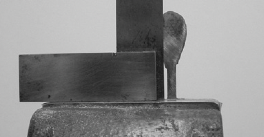
Fig. 10: Setting up for the pad bend
The final shaping of the touch end of the key should not be addressed until the key has been bent to the approximate angles required for its position. As the assembly comes out of the pickle, the metal is at its softest state. The pad end of the key is bent to approximately the correct angle by clamping the pad in a padded vise and pushing the shank back. It helps to make sure that the shank is at right angles to the top of the vise jaws. Do not attempt to do this operation without at least some sort of padding between the top side of the key and the vise jaw, or a mark which will be very hard to remove may be made where the bend occurs.
I like to give the touch a bit of doming, and the small amount of tapping with a ball peen hammer required to achieve this is also enough to work- harden and stiffen the touch. Before beginning the peening, I carve out the back edge of the keel using a ball file in a Foredom handpiece, having noted from my working drawings how much met- al can safely be removed from the keel to still leave sufficient metal where it will be required to form the pivot pin bearing. Peening out the touch will also allow a very small amount of shape correction, as may sometimes be required. The domed key will have a slight curve when viewed from the side, but it should in any case conform in profile to the plan drawings.
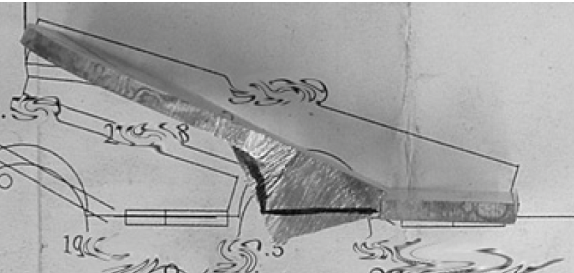
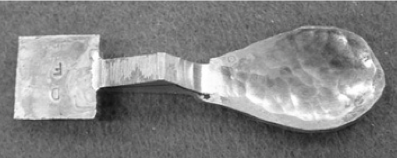
In Figure 15 we see a key that has already been shaped (in this case, shaped on the pantograph mill) and below it, the roughly domed key. This shows approximately how much metal has yet to be removed to bring the key to the desired size and shape.

Fig. 15: Finished and rough comparison
I shape the touch areas of the keys using a pantograph mill, but the shaping can certainly be done by hand, as I did it for years before acquiring the pantograph. I do not propose to talk about the pantograph process here, as the equipment is rare and the information borders on the esoteric. To shape the touch by hand, metal is removed from the edge of the touch by filing or on a disk or belt sander. As with any such freehand operation, it is important that you have a clear idea of what shape you want to end up with before you begin working. To do the shaping with files, the key needs to be clamped very firmly in a vise, with as much of the touch accessible as possible. A sensitive approach is required, to avoid bending the key. Figure 16 shows a key ready for filing: most of the excess material has been removed on a disc sander, and a guide line has been drawn on the touch with a Sharpie. The files shown in Figure 17 are 6” half-round files of bastard and second cut.

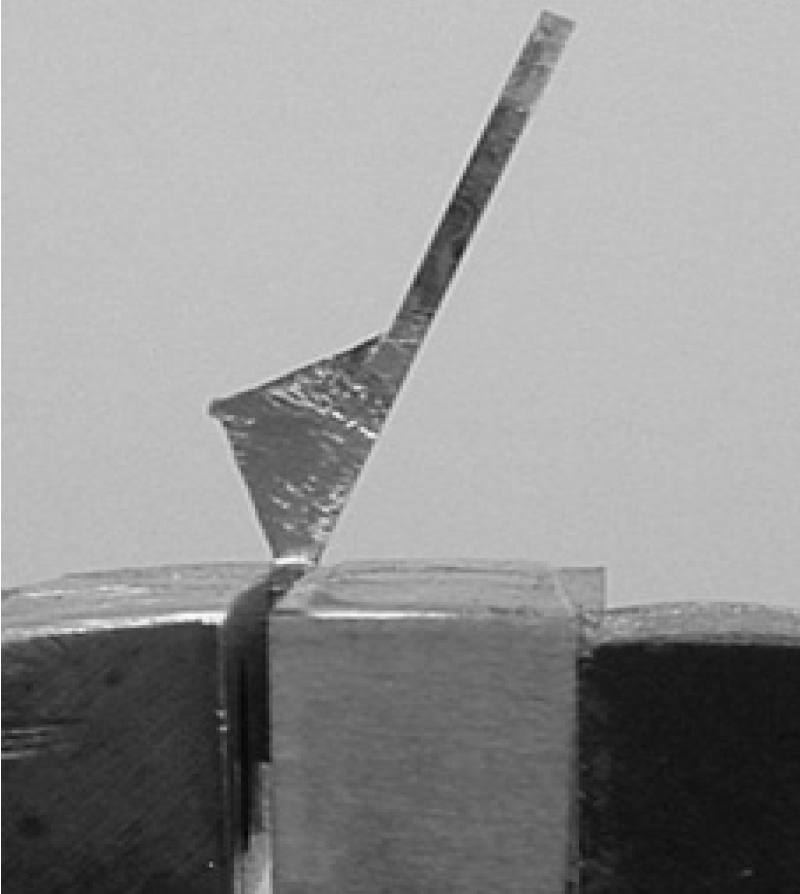
Fig. 16: Key in vise ready for filing to shape
When the keel is soldered to the cut-out blank, its “sense” of direction is established. As you proceed with the shaping of the touch, it is always good to keep a close eye on the symmetry and straightness of the key. If the touch appears to form something like a dog leg in relation to the shank, a certain amount of correction can be made by tapping the key while its shank portion is held very firmly in the padded vise. This correction can only be small, so it is best to obviate it altogether if possible, by careful alignment at the soldering stage, and careful observation of the progress of the shaping.
The pad ends of the keys are essentially rectangles of varying sizes. After the touches have been satisfactorily shaped, the pad rectangles need to be refined. This can be done either by hand, using files and power sanding, or on a milling machine.

Fig. 17: Filing key to shape
When the pad and touch areas of the key have been brought to their intended sizes and shapes, the keel may be finished. This typically involves removing a small amount of excess metal so as to leave the bottom of the keel more or less in line with the plane of the underside of the pad area. Then it remains only to make sure that the width of the keel is such that it will fit snugly into the slot it will occupy. A useful item to have for this process is a bit of wood with a slot cut into it in exactly the same way as the slots on the regulator itself are cut, to serve as a go/no-go gauge. I expect to have to do a small amount of hand filing on each key to achieve a satisfactory fit. When the keels fit snugly in the slots, the keys are ready for mounting. At this stage the visible surfaces of the key are all rough. No significant filing or sanding will be done on the touch area until after the springs have been riveted on, and the shanks are not sanded until after the pivot holes have been drilled.

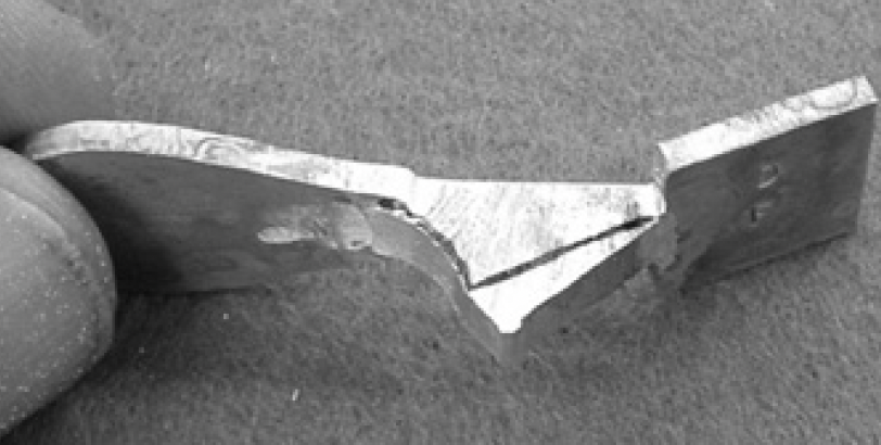
Fig. 18: Key shaped by filing
That brings us to the end of this section. In the next, we’ll be taking a look at the processes of bending the long keys and fitting keels to them, and then address the process of mounting the keys on the regulators.